
DC/DC Converter board RevD
- plug in power and test 2.3, 3.8, and 6V
- Label Starting from '21-SN on back
Testing
Testing DC/DC Converter board RevD on 2/17/21
| Board Label | 2.3V, measured | 3.8V, measured | 6V, measured |
| 21-SN | 2.33V | 3.84V | 6.09V |
| 22-SN | 2.33V | 3.84V | 6.10V |
| 23-SN | 2.33V | 3.85V | 6.10V |
| 24-SN | 2.32V | 3.83V | 6.08V |
| 25-SN | 2.33V | 3.83V | 6.09V |
| "6V is Bad" | 2.34V | 3.81V | 4.4V |
ADC Board Rev D
- measure input supply resistances on J16
Supply Pin R 2.3V 1 36k 3.8V 3 55k 6V 5 inf
- measure local supply resistances
5VA TP 200 5VD TP 5k 2V5 TP M-ohm 3V3 TP 1k 1V0 TP 600 1V8 TP 1.5k
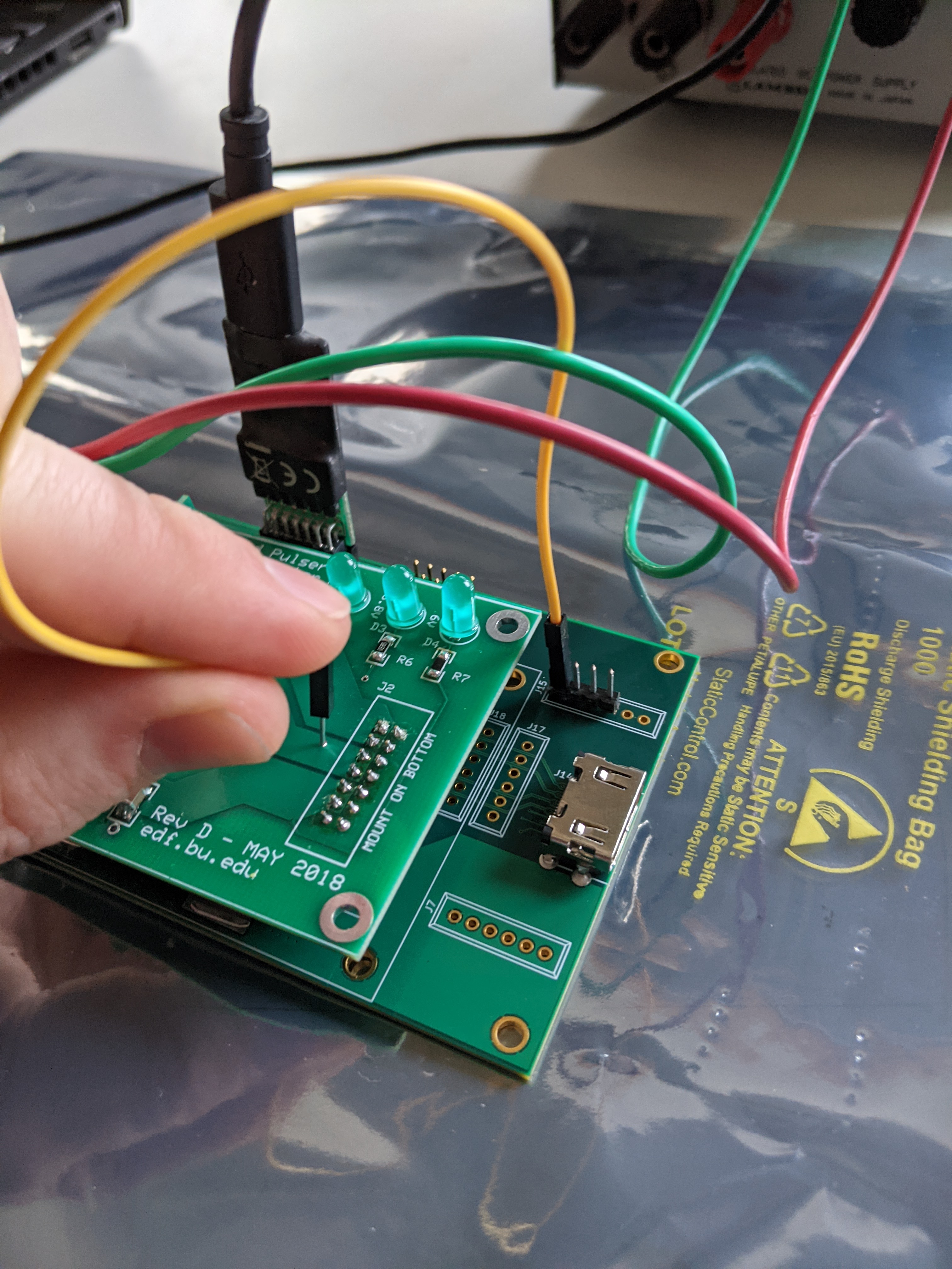
- Plug in DC/DC board (< 100mA on 12V)
- Use a jumper wire to enable the local power. Should give ~ 400mA on 12V in pic
- With jumper wire and a JTAG cable, see if the Artix shows up on the chain
- Program the Artix with a bit file (should be about 400mA on 12V) steps below
Connecting to ZYNQ at ADC setup. local for mike: (you gotta figure out BUTool on your own - ask Dan)
mikekremer@tesla.bu.edu$ cd ~/work/software/
mikekremer@tesla.bu.edu$ source env.sh
mikekremer@tesla.bu.edu$ BUTool -q 192.168.10.205
Setting the clk - Do this anytime you power the Zynq up (which you should do anytime you are changing HDMI connections).
BUTool> read TIMING_SYSTEM.CLK_SEL
                          TIMING_SYSTEM.CLK_SEL: 0x00000000
BUTool> write TIMING_SYSTEM.CLK_SEL 1
Write to register TIMING_SYSTEM.CLK_SEL
BUTool> read TIMING_SYSTEM.LOCK*
                          TIMING_SYSTEM.LOCKED_SYS: 0x00000001
                          TIMING_SYSTEM.LOCKED_TTC: 0x00000001
Power up an ADC board for programming, ADC board in slot two used for this example.
BUTool> read PWR_EN*
                                            PWR_EN: 0x00000000
                                          PWR_EN.1: 0x00000000
                                          PWR_EN.2: 0x00000000
                                          PWR_EN.3: 0x00000000
                                          PWR_EN.4: 0x00000000
BUTool> write PWR_EN.<number of ADC to power up, in this case 2> 1
Write to register PWR_EN.2
BUTool> read PWR_EN*
                                            PWR_EN: 0x00000002
                                          PWR_EN.1: 0x00000000
                                          PWR_EN.2: 0x00000001
                                          PWR_EN.3: 0x00000000
                                          PWR_EN.4: 0x00000000
Program ADC board using most recent .mcs file stored here. Plug JTAG into board and program with Vivado. follow this guide for how to program a device with the .mcs file. Vivado is gonna ask what kind of memory device you are programming, it's this one (s25fl128sxxxxxx0-spi-x1_x2_x4). After programming the board, re-init the board. NOTE: UNPLUG THE JTAG BEFORE TRYING THIS. you will fail to lock PWR_EN if the JTAG cable is still plugged in.
BUTool> initBoard <number of ADC to power up, in this case 2>
This last step might hang for a while (up to a minute), that's okay . Now check that the board successfully init'd from it's flashed firmware. output should like similar to this
BUTool> read ADCBOARD.<number of ADC to power up, in this case 2>.SYSTEM.*
                          ADCBOARD.2.SYSTEM.FW_VER: 0x19082101
                      ADCBOARD.2.SYSTEM.FW_VER.DAY: 0x00000021
                    ADCBOARD.2.SYSTEM.FW_VER.MONTH: 0x00000008
                      ADCBOARD.2.SYSTEM.FW_VER.REV: 0x00000001
                     ADCBOARD.2.SYSTEM.FW_VER.YEAR: 0x00000019
                      ADCBOARD.2.SYSTEM.SYNTH_DATE: 0x20201022
                  ADCBOARD.2.SYSTEM.SYNTH_DATE.DAY: 0x00000022
                ADCBOARD.2.SYSTEM.SYNTH_DATE.MONTH: 0x00000010
                 ADCBOARD.2.SYSTEM.SYNTH_DATE.YEAR: 0x00002020
                      ADCBOARD.2.SYSTEM.SYNTH_TIME: 0x00113930
                 ADCBOARD.2.SYSTEM.SYNTH_TIME.HOUR: 0x00000011
               ADCBOARD.2.SYSTEM.SYNTH_TIME.MINUTE: 0x00000039
               ADCBOARD.2.SYSTEM.SYNTH_TIME.SECOND: 0x00000030
Now get a current readout.
Testing
Testing ADC RevD
| Supply Resistance (Ohms) | Local Resistance (Ohms) | Current Draw | |||||||||||
| Board Label | 2.3V | 3.8V | 6V | 5VA | 5VD | 2V5 | 3V3 | 1V0 | 1V8 | With DC/DC Board | Draw with Jumper | After programming | JTAG Visible |
| 21-SN | 36k | 33k | 16M | 200 | 5k | 4.4M | 1k | 940 | 1.5k | <100mA | ~400mA | ~700mA | yes |
| 22-SN | 36k | 31k | 13M | 200 | 5k | in the M's | 1k | 890 | 1.5k | <100mA | ~400mA | ~700mA | yes |
| 23-SN | 36k | 56k | inf | 200 | 5k | 3M | 1k | 1.3k | 1.5k | <100mA | ~400mA | ~700mA | yes |
| 24-SN | 36k | 32k | 15M | 200 | 5k | 3.6M | 1k | 960 | 1.5k | <100mA | ~400mA | ~700mA | yes |
| 25-SN | 36k | 56k | inf | 200 | 5k | 17M | 1k | 600 | 1.3k | <100mA | ~400mA | ~700mA | yes |
| 26-SN | 36k | 56k | inf | 200 | 5k | 13M | 1k | 860 | 1.4k | <100mA | ~400mA | ~700mA | yes |
old boards
| Board Number | Current draw after programmed |
| 005 | ~700mA |
| 008 | ~700mA |
| 010 | ~700mA |
| 001 | ~700mA |
SMA boards
confirm that short is working "jumper cable on set up board" measure signal resistances, not shorted
Muon boards
look at pinout, signals not shorted
Testing GPIO on ADC cards (April)
Chris got the G-2 setup moved into a nice server rack enclosure.
There is space for 2 FMC carrier cards to be stacked on top of each other and for 4 ADC output cards with 1 GPIO expansion card each.
Currently configuring second FMC card
TODO - figure out how to run 1 test
>write TIMING_SYSTEM.CLK_SEL 1
Write to register TIMING_SYSTEM.CLK_SEL
>write PWR_EN.2 1
Write to register PWR_EN.2
>initBoard 2
>read ADCBOARD.2.SYSTEM.*
                          ADCBOARD.2.SYSTEM.FW_VER: 0x19082101
                      ADCBOARD.2.SYSTEM.FW_VER.DAY: 0x00000021
                    ADCBOARD.2.SYSTEM.FW_VER.MONTH: 0x00000008
                      ADCBOARD.2.SYSTEM.FW_VER.REV: 0x00000001
                     ADCBOARD.2.SYSTEM.FW_VER.YEAR: 0x00000019
                      ADCBOARD.2.SYSTEM.SYNTH_DATE: 0x20201022
                  ADCBOARD.2.SYSTEM.SYNTH_DATE.DAY: 0x00000022
                ADCBOARD.2.SYSTEM.SYNTH_DATE.MONTH: 0x00000010
                 ADCBOARD.2.SYSTEM.SYNTH_DATE.YEAR: 0x00002020
                      ADCBOARD.2.SYSTEM.SYNTH_TIME: 0x00113930
                 ADCBOARD.2.SYSTEM.SYNTH_TIME.HOUR: 0x00000011
               ADCBOARD.2.SYSTEM.SYNTH_TIME.MINUTE: 0x00000039
               ADCBOARD.2.SYSTEM.SYNTH_TIME.SECOND: 0x00000030
>load ~/work/software/scripts/nominalTiming.script
Write to register ADCBOARD.2.FP_PULSER.PROPOSED.ENABLE_2STEP
Write to register ADCBOARD.2.FP_PULSER.PROPOSED.CHARGE_START
Write to register ADCBOARD.2.FP_PULSER.PROPOSED.CHARGE_END
Write to register ADCBOARD.2.FP_PULSER.PROPOSED.DISCHARGE_START
Write to register ADCBOARD.2.FP_PULSER.PROPOSED.DISCHARGE_END
Write to register ADCBOARD.2.FP_PULSER.PROPOSED.STEP1_END
Write to register ADCBOARD.2.FP_PULSER.PROPOSED.STEP2_START
                       ADCBOARD.2.FP_PULSER.STATUS: 0x00000000
Write to register ADCBOARD.2.FP_PULSER.ENABLE
>load ~/work/software/scripts/extTrigger.script
Write to register TRIGGER.STATUS.ENABLE_PULSERS
Write to register TRIGGER.FREE_RUN.EN_FR_TRIG
Write to register TRIGGER.FREE_RUN.EN_EXT_TRIG
>load ~/work/software/scripts/startTriggering.script
Write to register TRIGGER.FREE_RUN.ENABLE
Should now see 5V pulses on J12 and J13
| Board Number | Notes |
| FMC1 | Good |
| FMC2 | Not locking clock |
| FMC3 | TBD |
| FMC4 | BAD |
Attachments (1)
- 2021-02-12 15.57.18.jpg (2.7 MB) - added by 4 years ago.